How I built a 2x80W amplifier (using power modules) |
Category: Do it yourselfWhat I started with ...
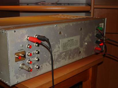
I started with some simple and common stuff: an old amplifier case made a log time ago, from which I took out what I could, apart from the transformer. The minimum efficiency of a B-class amp (as I wanted it to be) is 60%, so the power of the transformer is:Pout = 2 * 80 * 100 / 60 = 266 W Let’s say that a 250W minimum transformer is adequate. The one I had is a 300W custom made transformer. The big power of this transformer made me think about building something more powerful, good to carry at parties, or to listen indoors with the bass a maximum. The work as I sad before started from the metal box. 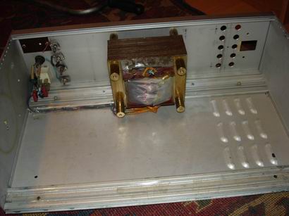 In the box I had just the On/Off button (in the back) with an uncoupling capacitor. This capacitor eliminates the possible noises which might appear in the primary inductor when powering up or down. The case isn’t very large, but it is high. So, I had to use this to my advantage by placing the electronic boards vertically. I started with the 5 inputs and a DECK output for recording. That means 12 RCA couplings. Initially there were 10, but I thought to use the square hole in the left, so I made a bigger board on which I mounted the RCA plugs to the panel. 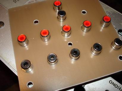 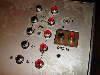 The writing on the case were made with “letraset”, in an age when printers were rare (yes, even dot-matrix ones). It’s still useful today, too bad it can’t be found anymore. The cable which goes to the coupling of the selector was a cheap one with 4 channels. Using 3 such cables, I took care of this problem, in an elegant fashion without many cables. 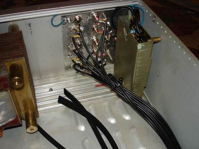 To the left you can see the preamp (From an old pickup) Signal and sensitivity
The problem is this: the DECK signals (from an old cassette player, TV, computer, etc) have amplitude of approximately. 300mv. The DECK name comes from the audio devices which were stacked-up to form an audio line. These devices had preamps and were hooked up to a big final amp, which had a sensibility of around 300mV. The old pickups have 2 types of output signals: a 300mV one and a direct 3mV one from the needle. This last one is much cleaner, because it doesn’t pass through the pickups amps (which can be low-quality). The problem with the low signals like the pickup one or the one from a microphone is that they can easily be influenced by electrical or magnetical fields. So, we have to use a high quality shielded cable. The shield problem applies to the preamp for the magnetic needle which has the purpose of bringing up the signal from 3mV to 300mV. It is shielded, because it has a high impedance on its entrance (>1 MOhm) and a sensibility of 305 mV. This means that the metal case which covers it has its purpose. Also, the amp was located far from the transformer to reduce the 50Hz noise which might disturb it. The wires for the entrance are short (so that they can’t act as antennas) and the amp will be plugged into a different source. Source with power modules
 To the left, perpendicular to the circuit board, are the low power +30V sources. The fuse is 1A and the stabilizers are 7818 and 7812. I mounted a lot of uncoupling capacitors, because these sources power the preamps and there mustn’t be any noise on the power line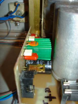 The rectifier bridgeThe rectifier bridge is an old Romanian 20PM5, 20A, 500V. It sounds good but it isn’t long lasting. By doing several tries, I reached the conclusion that around 10-12A, the 20PM5 bridge gets very very hot, and after 5 minutes fills up the room with smoke and kicks the bucket. As a witness I have a modest consumer of (only) 120W which took 12V@16-17A. Anyway, for around 9.6A (both channels) the bridge should hold. I mounted it directly onto the case because I didn’t want any heat problems. The 1.5 wires were tied directly to the transformer and to the board with the source. The entry selector and the “Loudness” effect (or tone compensation) are mounted entirely on the front panel. Here are the buttons for volume, muting, selector, tone control and LEDs which signal different things. 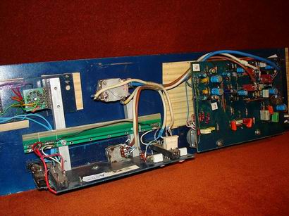 I know that the fabrication isn’t special. I used 90% second hand materials from PCs, radio-receivers, amps and other old Romanian stuff. I found the selector in an EPSON Stylus Color ’92-’93 printer. It was a color inkjet with 2 cartridges (WOW!!!) and 200dpi. The volume potentiometer has its own loudness plug. I took it from an old amp that somebody forgot at my place (can’t remember who). Volume and loudnessThe loudness effect works like this:
You can also see a balance potentiometer (with brown-white wires) and the mute button (to the left). The mute button is useful if you get a phone call and you’re too lazy to twist the volume knob. This button will decrease the sound level with 20dB. The corrector-preamp with 3 equalizersTo the left is my pride and joy: the corrector-preamp with 3 equalizers. It resembles the one in Winamp, but instead of 15 there are only 3. Usually 2 are enough (bass and treble). Why do I call it corrector? Because it is a tone corrector. If a melody has too many mediums you can cut them. If it has too little bass you can add it. You get it…. Why (again) preamp? Do you remember that 300mV input? Well, a good power-amp has a sensibility of around 1-1.5V! So this preamp raises a little bit the amplitude of the signal to 1.2V. (Over 1.2V you can get distortions which affect the sound quality). OK. Until now we have an excellent amp, perfect for hooking it up to a headset. Or a power module. This is a B-class power amp, capable of an 80W output on 4 Ohms and 50W on 8 Ohms.
What does it do? Well if you input a 1V signal you get a 13-18V output. It amplifies. A lot. And makes the speakers go boom-boom. Final amplifiers
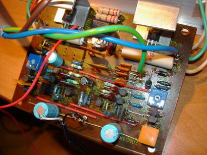
The components used are a mix of old and new ones. The passive components are old and the active ones are SGS-Thomson and National. The final transistors are 2N3055 and a complementary MJE2955. It’s interesting that MJE2955 didn’t exist a few years ago. The 2N3055 was on the market for lots of years without having a PNP variant. These transistors are excellent because they can take big currents. 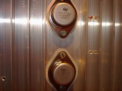 Here it is, finally, in the test phase. The first tests show an output on 8 Ohms of 18.9V. Without distortions. It’s a special performance. The power is aprox. 45W, with a sinusoidal entrance of 300mV. If you force it to 450mV, the output goes up to 19.8V, but paying the price of big distortions. This according is the hardest in the construction of a station. It is done with an oscilloscope and an amplitude signal generator. The adjusting is done by varying key resistances in the preamp. At the final amp, the problems are different. 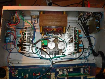 Circuit protection
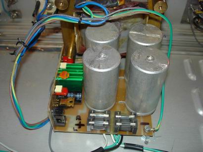
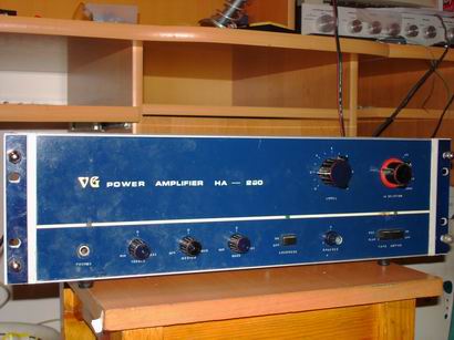
But let’s get back to our problems. The protection is another essential problem of an amp. It is shown below. 4 x 470uF capacitors (light-blue) are hooked up to the ground of the signal. If (God forbid) direct current shows itself on the exit, this exit signal isn’t connected to the ground but to the circuit below, which triggers a switch which disconnects the speakers. Also, the B class amps have a relatively long power-up (around 500ms) which transmits an unpleasant sound on either power-up or power-down, so this protection couples the speakers after around 3s of standby. And…that’s it. That’s a HI-FI audio amplifier.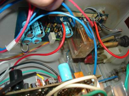 The audio-amp is ready. You close the case, (not very beautiful, I know) and …voila. Cheap, ugly, but good enough to be called HiFi !
Posted by: Andrei on February 28, 2006 at 20:19.
|
||
» Comments
hmm there are better transistors then ''new 2n3055''(chinese version,these can't give over 40W :S)
Posted by Alen on August 13, 2007 at 04:46 PM.
thank you..
how very useful. i am building my own amplifier... i will put it on my tricycle... thank you again for posting this here...
Posted by yvan on March 5, 2011 at 03:57 AM.
Random Article
Search
Feeds
All Categories
Articles
How to create the histogram of an image using PHP
How to convert an image to grayscale using PHP
How to check if an image is grayscale in PHP
Interchanging 2 variables without the use of a third
Error launching browser window:no XBL binding for browser
Convert the AOL user session collection to a MySQL database
Introduction to Matlab
Creating a customized session handling system in PHP (part II)
Creating a customized session handling system in PHP (part I)
Firefox crashing with Yahoo! Messenger
ADL Search for oDC
Video codecs explained
Browsershots
How to use Auto-Away Message with oDC
Create complete Windows XP disk with SP2 and all updates
Data Execution Prevention error message in Windows XP
Google Mars
Logarithmic scale graphs in Excel
Urban Dictionary (or wtf does l33t mean?)
Learn more about BIOS
Backup your Firefox and Thunderbird settings
Syndicate your Yahoo 360 profile
What is Google PageRank?
'Cannot Open the File: Mk:@MSITStore' Error Message
Get your Gmail with Mozilla Thunderbird
E-Books links
Change the size of your Explorer thumbnails
Remove previews from Windows Explorer
How can I turn off system beeps?
How do I disable Internet Explorer?
What are proxies or how do I protect my anonymity?
How to set aliases triggers or macros in MushClient
What is RSS?
Palm Zire 31 fast review
oDC Installation and Basic Configuration
How I built a 2x80W amplifier (using power modules)
Leech/HotLink Protection
How to block referrer detection?
How to find out your IP address
Getting started with Mushclient
What is spyware and how do I protect my PC from it?
Stumble Upon - random surfing around the web
Automatic file backup for Windows users
How can I read foreign language sites?
Protect your web surfing privacy!
What is BitTorrent?
No more ads! Adblock for Firefox
Why use Firefox instead of Internet Explorer?
How do I create my own Yahoo ID?